Module Elaboration (!Mod)
Elaboration of !Mod tags occurs over a number of stages:
The block is created as a DFBlock with its basic properties such as name, type, parent node, and description. Any options specified in the YAML description are attached as attributes, and the source file that contains the
!Moddescription is linked.The boundary IO described in the YAML are created and attached to the block as DFPorts. Again the name, attributes, type, description, and other parameters are filled in.
If required, automatic clock and reset ports are created and attached to the block. This stage can be disabled by using the
NO_CLK_RSTorNO_AUTO_CLK_RSToptions in the!Moddescription.The principal clock and reset signals are identified from the boundary IO, these will be distributed to any child modules with automatic clock and reset ports. Normally these will either be automatically created (as in step 3) or nominated by using the
AUTO_CLKandAUTO_RSToptions. However, if a block generates a clock then theclk_rootandrst_rootparameters can select an output port from a child module as the principal clock signal.Child modules instantiated by the
!Modare expanded, these run a nested elaboration process (starting again from point 1). If the elaboration depth is restricted, then the nested elaborations will only populate the boundary IO and not the child modules.Explicit connections between ports or between a port and a constant (as defined in the
!Modunder theconnectionsparameter) are resolved. A number of different constructions are supported, these are shown in a later section. Any points that have an explicit connection are not considered in the implicit connection stage as either initiators or targets, even if they are underpopulated (this is to improve the predictability of the result).Clock and reset signals are automatically distributed to nominated principal signals on child modules. Unlike all other signals, if a principal clock or reset has explicit outbound connections from stage (4) the implicit connections are still elaborated.
Implicit connections are elaborated - this is done in two passes. In the first pass connections are built using the ‘strict’ ruleset (both port name and type must match), in the second pass the ‘name’ rule is relaxed and only port type matching is required. In both passes only completely unconnected ports are considered - so if a port is partially populated in the first pass, it will be ignored in the second. A number of rules are used to build connections, these are covered in a later section.
If a register definition is included into the file where the
!Modis declared then the register set will be expanded and attached onto theDFBlock. The register elaboration process is discussed separately.The elaborator runs a check for any unconnected ports and logs a warning for each. These warnings are collected in the report and can be exported to a HTML summary.
The final stage is address map elaboration, which occurs if any
!Initiatorand!Targettags are listed within theaddressmapsection of the!Moddescription. The elaboration process is discussed separately.
Explicit Connection Rules
Where an explicit connection is formed between two ports, there are a number of rules that can be invoked.
One-to-One Explicit Connections
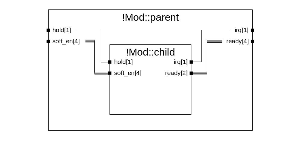 The most simple connection type has the same number of initiator ports as target ports and both end points carry the same number of signals. In this case the first signal within the initiator connects to the first signal in the target, and so on for as many signals are carried within the port (e.g. initiator[0]->target[0], initiator[1]->target[1], etc.). For example, in the above diagram
 soft_en on both Mod::parent (initiator) and !Mod::child (target) carry 4 signals. This would be described in the YAML syntax by:
- !Mod
  name: parent
  ...
  connections:
  - !Connect
    points:
    - !Point [soft_en]
    - !Point [soft_en, child]
As a result, the following connections will be built:
!Mod::parent.soft_en[0] -> !Mod::child.soft_en[0]
!Mod::parent.soft_en[1] -> !Mod::child.soft_en[1]
!Mod::parent.soft_en[2] -> !Mod::child.soft_en[2]
!Mod::parent.soft_en[3] -> !Mod::child.soft_en[3]
In a slightly more complicated scenario, the number of initiator and target ports are the same but the number of signals carried within each end differs. In this case, fan-out connections are built for the number of signals that the target port carries while the initiator signal index wraps. For example if in the above diagram ready on !Mod::child (initiator) carries 2 signals, whereas the port on !Mod::parent (target) carries 4 signals. This would be described as:
- !Mod
  name: parent
  ...
  connections:
  - !Connect
    points:
    - !Point [ready, child]
    - !Point [ready] # No module specified means port located on the parent
In this case the following connections will be built:
!Mod::child.ready[0] -> !Mod::parent.ready[0]
!Mod::child.ready[1] -> !Mod::parent.ready[1]
!Mod::child.ready[0] -> !Mod::parent.ready[2]
!Mod::child.ready[1] -> !Mod::parent.ready[3]
One-to-Many Explicit Connections
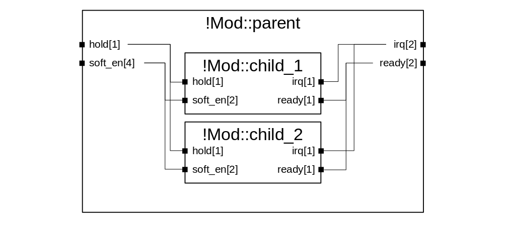 A more complex connection scenario is where there is one parent port and multiple target ports, and so a fan-out is constructed. The connectivity depends on the number of signals carried within the parent port, and the total number of signals carried in all of the child ports.
In the diagram above, two different results of one-to-many connectivity are shown. The first case is a true fan-out, where one signal is connected to multiple target ports. In the diagram this is demonstrated where hold on !Mod::parent (initiator) is connected to hold on both !Mod::child_1 and !Mod::child_2 (targets). This would be described as:
- !Mod
  name: parent
  ...
  connections:
  - !Connect
    points:
    - !Point [hold]          # Initiator
    - !Point [hold, child_1] # Target
    - !Point [hold, child_2] # Target
This results in the following connections:
!Mod::parent.hold[0] -> !Mod::child_1.hold[0]
!Mod::parent.hold[0] -> !Mod::child_2.hold[0]
The second case is formed of unique connections, where each signal within the target port is connected to a different signal on a different block. In the diagram this is demonstrated where soft_en on !Mod::parent (initiator) is connected to soft_en on both !Mod::child_1 and !Mod::child_2 (targets). This would be described as:
- !Mod
  name: parent
  ...
  connections:
  - !Connect
    points:
    - !Point [soft_en]          # Initiator
    - !Point [soft_en, child_1] # Target
    - !Point [soft_en, child_2] # Target
This results in the following connections:
!Mod::parent.soft_en[0] -> !Mod::child_1.soft_en[0]
!Mod::parent.soft_en[1] -> !Mod::child_1.soft_en[1]
!Mod::parent.soft_en[2] -> !Mod::child_2.soft_en[0]
!Mod::parent.soft_en[3] -> !Mod::child_2.soft_en[1]
Note that as with one-to-one connections, initiator signal count will wrap if more connections are formed than are carried within the port. If the signal count of soft_en on !Mod::parent was reduced from 4 to 2, then the connectivity to !Mod::child_1 and !Mod::child_2 would become:
!Mod::parent.soft_en[0] -> !Mod::child_1.soft_en[0]
!Mod::parent.soft_en[0] -> !Mod::child_2.soft_en[0]
!Mod::parent.soft_en[1] -> !Mod::child_1.soft_en[1]
!Mod::parent.soft_en[1] -> !Mod::child_2.soft_en[1]
Many-to-Many Explicit Connections
Currently this connectivity type is not supported. This means you cannot create connections where there are multiple initiator and multiple target ports, but the number of each is not equal.
Tied to Constant Value
For input ports (or output ports on the parent block) with primitive types (e.g. wire) it is possible to tie the value to a constant in the YAML description. This could be used to tie off dangling input IO on a complex IP that is reused in multiple places for different purposes. In this case a connection is formed with the initiator as a constant and the target as the primitive port. This would be described in YAML as:
- !Mod
  name: parent
  ...
  connections:
  - !Connect
    constants:
    - !Const [5]
    - !Point [my_value_to_tie_off, child]
Clock and Reset Distribution Rules
Clock and reset signals are treated in a different fashion to other signal types. Firstly, to provide some context, BLADE has a concept of ‘principal’ ports, which are signals nominated either automatically by the tool or within the source YAML to have special significance. Examples of principal signals are the main clock and reset to a block, which may need to be distributed to child modules.
In the case where neither NO_AUTO_CLK_RST nor NO_CLK_RST are present within the !Mod's option list, clock and reset signals are created and injected during elaboration (see step 1 above of the !Mod elaboration process) and are nominated as the principal signals of the block.
Where either NO_AUTO_CLK_RST or NO_CLK_RST is specified, the designer can nominate a prinicipal port for clock or reset by using the AUTO_CLK and AUTO_RST options on the relevant !HisRef:
- !Mod
  name   : my_mod
  options: [NO_AUTO_CLK_RST]
  ...
  ports  :
  - !HisRef [clk_s, clock, 'Main clock signal', 1, SLAVE, '', [AUTO_CLK]]
  - !HisRef [rst  , reset, 'Main reset signal', 1, SLAVE, '', [AUTO_RST]]
  - !HisRef [clk_2, clock, 'Secondary clock'  , 1, SLAVE, '', []        ]
  ...
There is also the option to use the output of a child block as the prinicipal clock or reset, this is useful for scenarios where a clock generator or gate is instantiated. In this case, the clk_root and rst_root attributes must be set on the parent !Mod - this is demonstrated in the following example:
- !Mod
  name    : my_wrapper
  options : [NO_AUTO_CLK_RST]
  clk_root:
  - !Point [clk_out, clk_gen]
  rst_root:
  - !Point [rst_out, clk_gen]
  ports   :
  - !HisRef [clk, clock, 'Primary clock signal', 1, SLAVE, '', [AUTO_CLK]]
  - !HisRef [rst, reset, 'Primary reset signal', 1, SLAVE, '', [AUTO_RST]]
  ...
  modules :
  - !ModInst [clk_gen, clock_generator, 'Clock generator'   , 1]
  - !ModInst [reg_blk, registers      , 'Register interface', 1]
  ...
  connections:
  - !Connect
    points:
    - !Point [clk]
    - !Point [clk_in, clk_gen]
  - !Connect
    points:
    - !Point [rst]
    - !Point [rst_in, clk_gen]
  ...
Note that while the primary clock and reset signals are marked as AUTO_CLK and AUTO_RST, they are not routed to the child nodes. Instead the markers are used when !Mod::my_wrapper is instantiated in a parent block in order to route the clock and reset signals to the instance. Within !Mod::my_wrapper the automatic clock routing to child nodes such as !Mod::reg_blk will obey the points defined by clk_root and rst_root.
One other point of note is that unlike other signals, principal clock and reset signals can be both explicitly and automatically routed. Explicit routing occurs first (step 4 of module elaboration), then automatic clock/reset distribution runs (step 5). Principal signals will still be used as initiators even if they are already driving targets, however targets that are already driven will be ignored during the automatic routing phase even if they are under populated (i.e. port carries more than one signal and some signals within the port remain unconnected).
Implicit Connection Rules
Implicit connectivity is a trickier problem to solve as the tool needs to make decisions on how the designer intended the design to be connected up. The tool needs to be able to make three different types of connections: parent-to-child, child-to-parent, and child-to-child. Correct connections are inferred from both the name and type of each endpoint. Two rules overarch implicit connectivity:
Connections can only be formed between a compatible pair - for example an input port on the parent can be connected to an input port on a child or an output port on the parent, but it cannot be connected to any input port on the parent.
Automatic connections will not be formed between outputs and inputs of the same block, if this is desired then an explicit connection must be declared.
Automatic routing occurs in two phases. In the first phase (strict) both the name and the signal type of the endpoints must be an exact match - for example a port of type wire on the parent !Mod called enable will only be connected to ports on child modules with the name enable of type wire. In the second phase (relaxed) only the signal type of the endpoints is considered when forming connections - for example a port of type wire on the parent !Mod called disable will be routed to any unpopulated ports on child modules of type wire. Note that both phases only examine ports that are completely unconnected, therefore any underpopulated ports left after phase 1 has completed will not be further connected in phase 2 - this is to reduce the risk of a misconnection being formed. Any ports that remain unconnected or underpopulated after both phases should be detected and warnings raised.
However, in a complex design it may be necessary for some signals to be tied off where an IP is reused in multiple different scenarios. As documented in a previous section, primitive input signals can be tied to a constant value using a !Connect tag with the initiator being a !Const tag. For more complex input ports, or where an output port should be left unconnected, the tool allows a list of defaults to be provided. This is demonstrated in the example below:
- !Mod
  name    : my_block
  ...
  modules :
  - !ModInst [reg_blk, registers, 'Register interface', 1]
  ...
  defaults:
  - !Point [dma_ctrl, reg_blk]
  ...
In this case, all ports on the child reg_block will be connected following normal explicit and implicit elaboration rules - but the port dma_ctrl will be left unconnected, and the tool will not warn about it dangling, even if an identically named port with the same type exists on another child, or on the parent.
The same structures of fan-in and fan-out connectivity are supported as explicit connections. The connection builder works through the initiators for each case, and tries to identify as many targets as possible. The algorithm tracks the last connected signal index for each initiator, wrapping back to zero every time the signal count of the port is exhausted.
API
-
blade.elaborate.module.build_tree(module, instance_name, parent, scope, max_depth=None, depth=0)¶ Recursively convert the Phhidle document definition of the design into a DesignFormat hierarchy.
- Parameters
module – The definition of this block
instance_name – The name of this instantiation
parent – The parent block (as a DFBlock)
scope – The Phhidle document scope for resolution
max_depth – The maximum depth to elaborate to
depth – The current depth we are working at
- Returns
The elaborated block complete with ports, children, etc.
- Return type
DFBlock
-
blade.elaborate.module.elaborate_c2c_connections(block, c_ports, relaxed=False)¶ Elaborate all implicit connections passing between child blocks.
- Parameters
The block we are working within (block) –
The unconnected child port set (c_ports) –
Use relaxed matching where only type examined (default (relaxed) – False)
-
blade.elaborate.module.elaborate_c2p_connections(block, p_out, c_ports, relaxed=False)¶ Elaborate all implicit connections passing from a child block to the parent.
- Parameters
block – The block we are working within
p_out – The parent’s unconnected outbound port set
c_ports – The unconnected child port set
relaxed – Use relaxed matching where only type examined (default: False)
-
blade.elaborate.module.elaborate_module(top, scope, max_depth=None)¶ Elaborate a !Mod tag instance, expanding hierarchy and resolving connections up to the maximum requested depth.
- Parameters
top – The top-level !Mod to elaborate from
scope – An ElaboratorScope object containing all documents included directly or indirectly by the top module.
max_depth – The maximum depth to elaborate to (optional, by default performs a full depth elaboration - max_depth=None)
- Returns
Contains the elaborated block and all interconnects used
- Return type
DFProject
-
blade.elaborate.module.elaborate_p2c_connections(block, p_in, c_ports, relaxed=False, bidir=False)¶ Elaborate all implict connections passing from the parent block to a child.
- Parameters
block – The block we are working within
p_in – The parent’s unconnected inbound port set
c_ports – The unconnected child port set
relaxed – Use relaxed matching where only type examined (default: False)
bidir – Handling bidirectional ports (default: False)
-
blade.elaborate.module.list_unconnected_ports(block, xmap, defaults)¶ Search through the parent and child blocks for all unconnected ports
- Parameters
block – The block to search through
xmap – The expansion map of child modules
defaults – A list of Phhidle !Points that tie signals off
- Returns
Returns namespace of all unconnected parent and child ports
- Return type
namespace
-
blade.elaborate.module.resolve_mod_inheritance(mod, scope)¶ To support features such the automatic decoder flow, a !Mod must be able to extend from other !Mod definitions - carrying forward options, children, ports, and connectivity. This can happen recursively. This function returns a merged !Mod, taking into account the inheritance.
- Parameters
mod – The !Mod to resolve
scope – The Phhidle document scope to use for resolving !Mod
- Returns
The resolved !Mod with inherited properties
- Return type
-
blade.elaborate.module.resolve_point_to_ports(block, xmap, point)¶ Resolve the !Point connection to a list of ports (it can be multiple ports as module instantiation can have a count > 1)
- Parameters
block – The parent block to resolve within
xmap – The expansion map of child modules
point – The !Point instance to resolve
- Returns
List of !DFPorts expanded from the provided !Point
- Return type
list